Mobile : +91 9488 444777, +91 94868 58777
Landline : +91 9488 444777
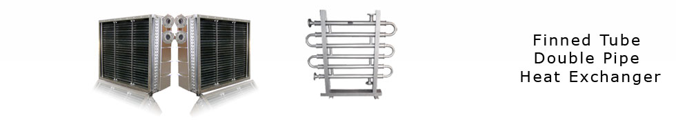
Finned Tube Heat Exchangers
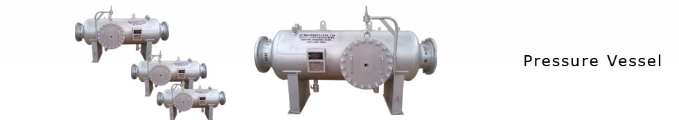
A Finned Tube heat exchanger, is simply a pressure vessel which cools a circulating fluid within finned tubes by forcing ambient air over the exterior of the tubes. Also, This is known as device for rejecting heat from a fluid directly to ambient air. The main advantage of an FTHE is that it does not require water, which means the plants requiring large cooling capacities are need not be located near a supply of cooling water.
Codes / Specifications
- ASME Section I & VIII Division 1
- TEMA
- API 660
- API 661
- National Board
Quality Control
- Inspection Agency: HSB Global Standards
- ASME Certificates U and S
- NB certification
- Radiography, Liquid Penetrant, Ultransonic, Hardness,
Mag Particle (Wet and Dry), Surface Roughness,
Tensile, Chemical and Physical Analysis.
Finned Tube Heat Exchangers (FTHE) /Air Fin Coolers:
Method of Heat Transfer:
An Finned Tube heat exchanger, is simply a pressure vessel which cools a circulating fluid within finned tubes by forcing ambient air over the exterior of the tubes. Also, This is known as device for rejecting heat from a fluid directly to ambient air. The main advantage of an FTHE is that it does not require water, which means the plants requiring large cooling capacities are need not be located near a supply of cooling water.

Purpose of Finned Tube Heat Exchangers :
1. Finned Tube heat exchangers are generally used where a process system generates heat which must be removed, but for which there is no local use. This is One of the simplest ways is to use the ambient air.
2. They are usually used when the outlet temperature is more than about 20 deg. F above the maximum expected ambient air temperature. They can be used with closer approach temperatures, but often become expensive compared to a combination of a cooling tower and a water-cooled exchangers.
3. The most important thing is, They are a "green" solution as compared to cooling towers and shell and tube heat exchangers because they do not require an auxiliary water supply (water lost due to drift and evaporation, plus no water treatment chemicals are required).
Types of Finned Tubes:
Finned Tubes are most important part of the Heat exchanger which affect the efficiency of the Air Cooled Heat Exchanger. Below mentioned some types of Finned Tubes manufactured by us.
"L" Tension FINS
"L" Fins are Tension wound to base Tubes
Maximum working temperature =130 °C/270 °F
Atmospheric corrosion resistance: Acceptable
Mechanical resistance: Poor
"LL" Fins
Overlapped L" Fins are an Economical alternative for Extruded Tubes
Maximum working temperature =165 °C/330 °F
Atmospheric corrosion resistance: Acceptable
Mechanical resistance: Poor
"KL" FINS
Knurled Tubes Enhance the bondage of the L-fins
Maximum working temperature =250 °C/480 °F
Atmospheric corrosion resistance: Medium
Mechanical resistance: Acceptable
EXTRUDED FINS
Fins are produced though in thread rolling process
Maximum working temperature = 285 °C/545 °F
Atmospheric corrosion resistance: Excellent
Mechanical resistance: Excellent
"G" EMBEDDED FINS
Fins are mechanically embedded in a groove to the base plate
Maximum working temperature = 400 °C/750 °F
Atmospheric corrosion resistance: Poor
Mechanical resistance: Acceptable
TUBE MATERIALS INCLUDE:
- Carbon Steel, Seamless, and Welded
- Stainless Steels, Seamless, and Welded
- 2205 Duplex
- Copper, Copper Nickel, Admiralty Brass
- Titanium
Thermal Design :
The design of FTHE are made based on
1. FTHEs are subject to a wide variety of constantly changing climatic conditions which pose problems of control not encountered with shell and tube exchangers.
2. Then, We will work on economic balance between the cost of electrical power for the fans and the initial capital expenditure for the equipment. A decision made as to what ambient air temperature should be used for design. Air flow rate and exhaust temperature are initially unknown and can be varied in the design stage by varying the number of tube rows and thus varying the face area. The basic heat transfer relationships that apply to shell and tube exchangers also apply to FTHEs.
The fundamental relation is the Fourier equation:
Also, Q = Fluid Mass Flow rate x cp x Delta T
Then, 1. Fan Selection,
2. Drive Required for Fan. (Horse power Requirement).
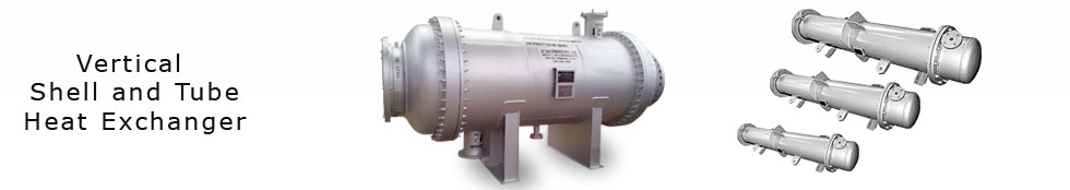
Components of Finned Tube Heat Exchanger:
- Tube bundle – contains finned tubes
- Tube sheet
- Plug sheet
- Header plug
- Fan
- Fan ring
- Plenum
- Header
- Nozzle neck, flange
- Drive assembly
- Column support
- Drives & transmission
- Air flow control
- Vibration monitoring system
- Bearing sets and drive shafts
- Fan louvers
- Tube supports
In all above Types of Heat Exchangers , Main Heat Transfer Elements are:
1. Tubes,
2. Fins and
3. Fan (Actuating Device for Heat Transfer)
Tube Material Selection:
The material selection is made as per Process Application, And Cost of Heat Exchangers
We use following materials for Constructions:
1. Carbon Steel
2. Stainless Steel
3. Admiralty brass,
4. Copper,
5. And Exotic alloys.
Fin Materials Selection :
1. Aluminum Fins are mostly used one,,
2. Copper Wire Fins for Specific Applications.
3. Galvanized Iron Fins – For Low cost Projects.
Also We use Cast Zinc bands at the end of the Tubes and Tube Supports, To Prevent Fins From Unwrapping.
Fins Selection:
We choose the Appropriate Fins based on Specific Applications Like Below,
1. L and Overlapped L Fins :
The L fin design is for design temperatures less than 300 degrees Fahrenheit. This fin offers a certain degree of atmospheric protection of the tube wall against corrosion. The broad contact surface between the tube and the finning enhances heat trasnfer. This fin design is the most economical. The overlapped L fin design is for customers who want an increased level of tube coverage. The foot of the L fin is simply overlapped onto the previous L foot. This results in a slightly higher level of tube corrosion protection and allowable design temperature. This fin is created by forming an aluminum strip into an L-shape which is then tension wound around the primary tube. Each L section is positioned against each other to ensure complete tube coverage.
2. Embedded or G fins :
The Embedded fin is designed for high temperature and / or cyclical applications.
3. Extruded Fin :
Typically extruded fins are used in corrosive atmospheric conditions, such as off-shore applications, or at operating temperatures less than 550 degrees Fahrenheit. This fin design is the least economical as compared to the other fin types, primarily due to the increased amount of aluminum used (~40%) and the increased labor required to manufacture. However this increased cost can be offset if a lower grade parent tube material is used. The extruded fin is manufactured by compressing an aluminum bloom, or sleeve, onto the parent tube. The bloom is exposed to extremely high pressures which essentially "grows" the fins into the final fin profile. The process produces an extremely strong joint with excellent heat transfer capabilities.
Standards In Finned Tube Heat Exchangers :
Also, These include such items as galvanizing vs. painting, types of headers, maintenance walkways and platforms, controls, and external loads on the cooler.
Also We follows Standards in Heat Exchanger Constructions.
Finned Tube Heat Exchanger Applications:
All our Heat Exchangers are customized for each client's needs, thus providing the ability to service nearly every air cooler application. Our air coolers are installed throughout the world in the following applications:
- Hydrocarbon process and steam condensers
- Large engine radiators
- Turbine lube oil coolers
- Turbine intercoolers
- Natural gas and vapor coolers
- Combustion pre-heaters
- Flue gas re-heaters
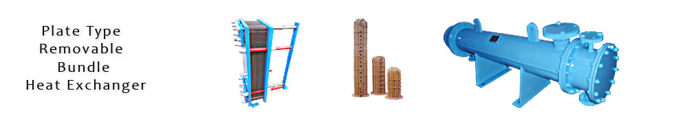
Plate-fin heat exchanger is one of the most efficient compact heat exchanger. The gaps between constitute a fluid layer. A core is made of a great number of layers. The exchanger can be made of one or more cores. The number of plate and fin layers, the size of the plates and fin, the height of the fin and the type of fin are engineered for optimum performance. The core is assembled (stacked) and typically held together by tack welding a weld rod to the top and bottom layer of the core. The stacked core is then placed within a fixture that exerts force on the individual pieces to keep them in contact. The part is then vacuum brazed in an environmentally-controlled room to ensure high quality and reliability. After brazing the core is typically heat treated or aged in order to increase its strength. Manifold ducting and mounting brackets are then welded in place as required, and any required paint or coating can be added.
Plate-fin heat exchangers can be designed for use with any combination of gas, liquid, and two-phase fluids.
Finned Tube Heat Exchangers